The HFp Concept
The HFp design is unique. The antenna consists of a series of 18" long elements, about 3/8" in diameter, with threaded brass inserts in each end. They screw together by means of brass connectors, which are called Inter-Element-Connectors (IECs).
There are four types of elements, which are electrically different from each other, and are also different end-to-end. Each of the elements is identified by a label at one end: one-stripe, two-
stripes, three-stripes, and a shorter "zero-stripes".
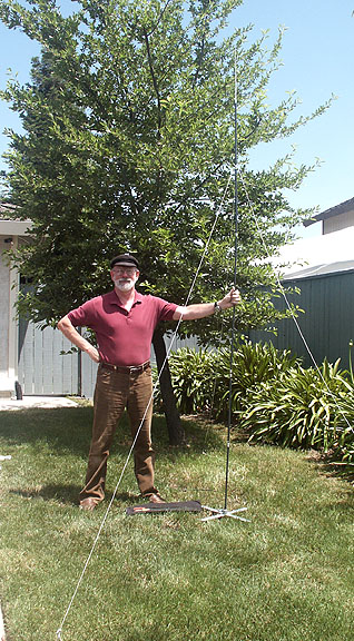
Here is the HFp-Vertical, set up for 40 Meters. On this band, it stands about 9.5 feet tall. (On 20 Meters, it's about 6 feet.) You can see the guy lines, and the silver pull-up whip on the top, but, if John didn't have his hand on it, you might not even notice the rest of the antenna!
Not shown in this picture are the three radial wires (included) which attach to the base plate, and are necessary for proper operation of the antenna. They come spooled on plastic reels, and are marked at the correct tuned length for each band. A write-up which you should read explains the bad things which can happen if random-length radials are used on a ground-mounted vertical antenna.
Various options are available for the HFp-Vertical, as seen here.
The mix of elements, and the orientation - "stripes-up" or "stripes-down" - determines the resonant frequency of the antenna.
The HFp-Vertical kit comes with the element mix required to set up a ground-mounted vertical antenna on the Ham bands from 40M through 6M, and a laminated card which shows the configuration for the Ham bands, including which mark to unroll the radials to, and the length of the pull-up whip. The Dipole uses the same elements, and has its own configuration card.
A note to CAP and MARS operators - the HFp-V is so configurable that it can be set to resonate at ANY frequency between 6.5 and 54 MHz. And, an optional add-in coil allows tuning the antenna to frequencies in the 60M, 75M, and 80M bands.